Current revision is 2.06
OptLowpass™ is a specialized program written to expedite the design of transmitter output lowpass filters,
written specifically for the HF amateur radio bands.
Here are some pertinent features:
- OptLowpass is 32-bit Windows® electrical filter design program written specifically to help the radio amateur
design transmitter output harmonic-suppressing lowpass filters.
- It is based on the author's article "Harmonic Filters, Improved" which was in the September/October 1998 issue of
QEX, an ARRL publication.
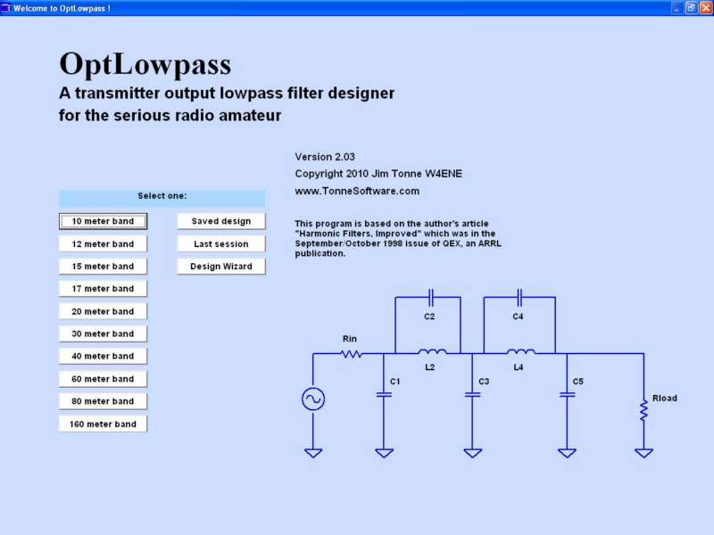
- On startup, the program presents pre-designed lowpass filters for each of the HF amateur bands, using ideal parts
values as outlined in the above-mentioned article. You may also recall the last design session, recall a
previously-saved design or invoke the Design Wizard.
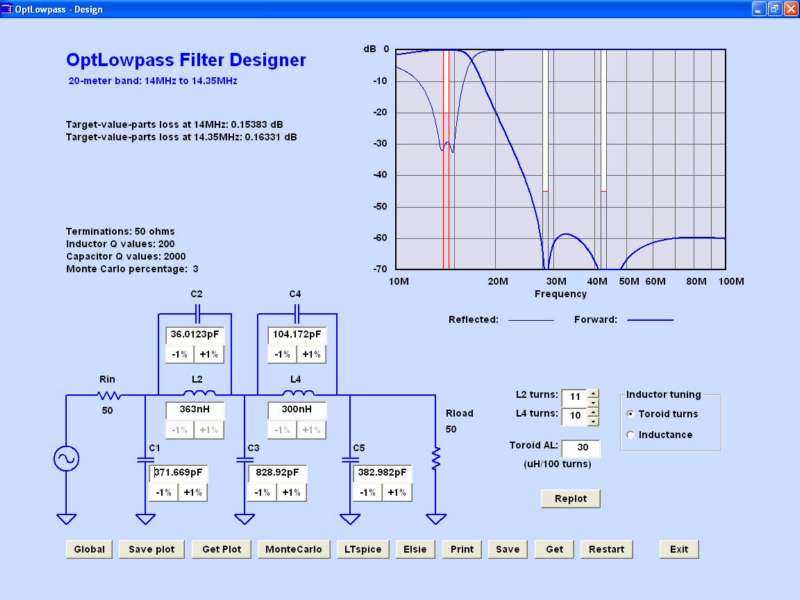
- The design page shows the schematic of the filter as designed and a plot of the responses of that filter (both
transmission and reflection).
- The capacitors' ideal values can then be adjusted by entering values in textboxes or they can be "tuned" upward or
downward in 1% steps with the results immediately replotted right on the same screen.
- The inductors' values can be adjusted by inductance value (textbox entry or by percent steps, like the
capacitors).
- A design as edited can be saved using a user-specified name and path for recall later.
- All of the various data files are in ordinary text format for ease of editing or examination outside the
program.
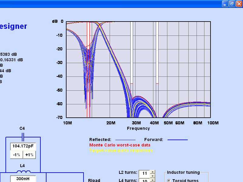
- Pressing the Monte Carlo button results in an examination of the filter using a user-specified percentage
plus/minus random parts distribution. Worst-case values are clearly shown.
- Items that are probably going to be used "globally" (on all bands, for a given installation) are stored in a Global
Default file and are read into the program at startup. These can be edited and saved by the user. Examples of the items
stored in the global defaults file are system impedance (50?), inductor Q values (200?), capacitor Q values (2000?) and
so on.
- For maximum quality of printed output, the output to the printer is not a "screen dump" but instead is from a
routine which writes directly to the printer. The quality of that printout will be limited only by that printer,
commonly several hundred pixels per inch. The printer output on one sheet contains the schematic with parts values
along with the plot of responses and essential design information.
- Click on the "Elsie" button to write a file to drive Elsie the filter design and analysis program for followup
filter examination in even greater detail.
- Click on the "LTspice" button to write a ready-to-run LTspice file to drive the LTspice simulator for further
examination, especially involving component voltage and current stress issues.
(Tonne Software has no connection with Linear Technology Corporation.)
- Now includes 600 meter and 2200 meter band lowpass filter designs.