Meter - AppNote #1
This page was written to illustrate the mechanics of changing a meterscale using, of course, Meter as the
scale design aid. It does not cover the design of a particular scale but rather covers "how to do it" in some practical
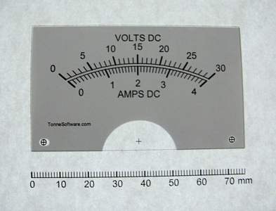
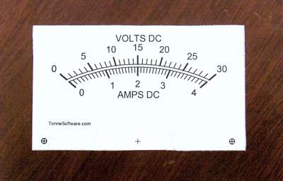
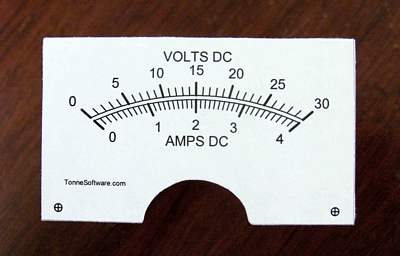
detail.We are assuming that you have designed a scale to your specifications using the program Meter. For our example we have a two-scale plate, 0-30 volts and 0-4 amperes. And now it is time to mount the scale on the underlying metal plate.
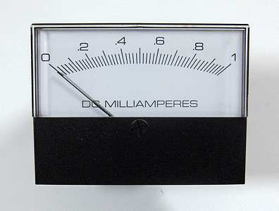
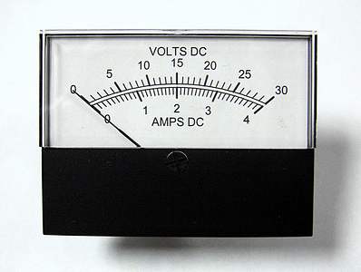
Here we see a meter that we are going to modify by giving it a new scaleplate.
Open the case to access the plate on which the scale is printed. Here we see that perhaps some glue is used to seal the case. Carefully break the seal or otherwise open the case. For those cases that are held together with screws simply unscrew them.
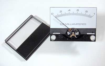
Remove the face (front) of the assembly and set it aside.
It is very important to keep the entire work area very clean.
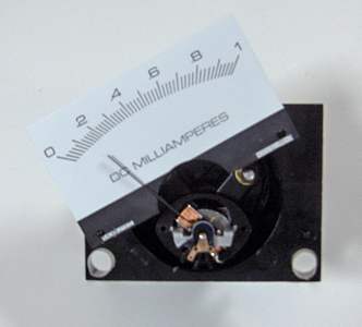
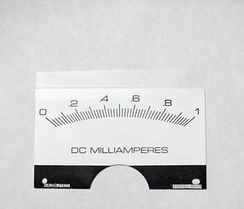
Remove the plate but don't let it touch the pointer.
In this meter the plate was held in place by two small "dimples." To remove the plate without touching the pointer it was rotated to the left.
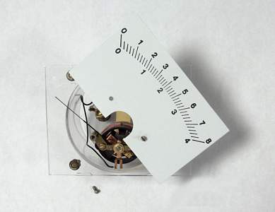
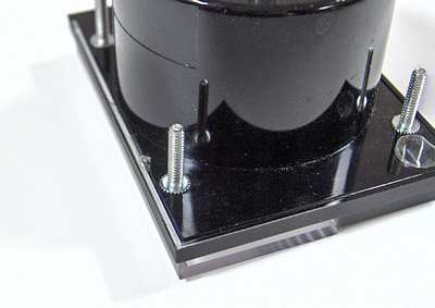
In this meter the plate was held in place by two screws. To remove the plate it was rotated to the right.
Don't let the plate touch the pointer.
Now we have the plate separated from the meter case.
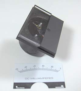
Place the front cover back on the case so that the interior portion of the meter will be kept clean.
An obstacle that might be encountered is a plate with a "mirror" on it. This can show through most papers on which a scale would be printed. The mirror might very well be a thin sheet of plastic film which has been metalized. The best way to minimize the possibility of the mirror showing through the printed paper is to use a paper which has sufficient thickness. Alternatively you could add another layer of paper between the plate and the printout.
The paper should be bright white and smooth. It does not need to be thick. Ye scribe has used old photographs on which to print.
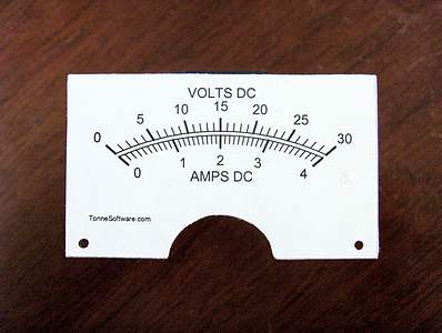
Now we can make various measurements and put them into the program Meter.
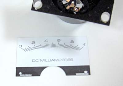
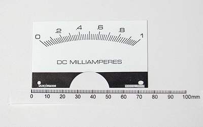
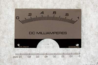
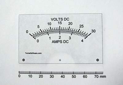
Measure the plate width (76 mm here).
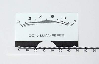
Measure the plate height (45 mm here).
The measurement of width and height are not critical. If you wish, round them up to the next higher millimeter or more.
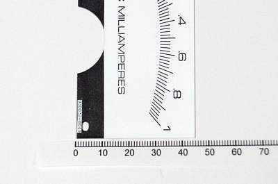
Measure the distance from the plate bottom to the bottom of the arc (32 mm here). In the program Meter this item is called "Bottom to scale ceiling."
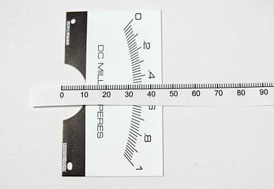
Now measure the separation between the mounting holes (67 mm here). This must be an accurate measurement.
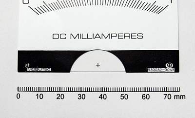
Print a scale and confirm that the mounting hole separation is correct, as shown here by laying the plate on top of the printout.
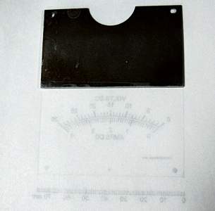
Place the printout on a window or light table, with the printing side away from you.
Place the reverse side of the metal plate against the non-printed side of the newly-printed scale. (By doing this, the original lettering will not show through the new paper scale.)
If there is some kind of printing on the back side of the original plate, it must be removed using an appropriate solvent. We need a clean surface, without any lettering or marking, onto which we will attach our new scale.
Place the metal plate on the printout with the original scale facing toward you; the plain metal side of the plate will be facing back toward the paper.
Line up the mounting holes on the paper with those on the plate. If the paper is thick enough or opaque enough that the mounting holes cannot be seen, then use a pin to make a small hole ("pinhole") in the middle of each of the printed mounting holes. Center the holes on the metal plate over the pinholes on the paper.
Use plastic tape to form a "hinge" at the top of the plate.
(In this photo the hinge cannot be seen. The mounting holes on the plate not appear to be lined up with those on the printout but this is because the plate is displaced from the printout.)
Remove the assembly from the window (or light table) and turn it over to view it from the front side, with the newly-printed scale facing you.
If necessary, reposition the plate on the printout so that the mounting holes on the plate line up precisely with those on the printout.
Place the assembly on a worktable with the printing side down (away from you). In this photo the plastic tape "hinge" can be seen.
Lift up the plate by that "hinge" as shown.
Use a light application of a spray adhesive on the plate and optionally on the paper. Spray adhesives work much better than adhesives that are applied using a brush.
Do not use "rubber cement" because the scale will become discolored over time.
Ye scribe uses 3-M "Spray Mount" Artist's Adhesive. Surely other adhesives may be used.
Lower the plate back down to the printout, turn the assembly over and carefully press the paper against the plate.
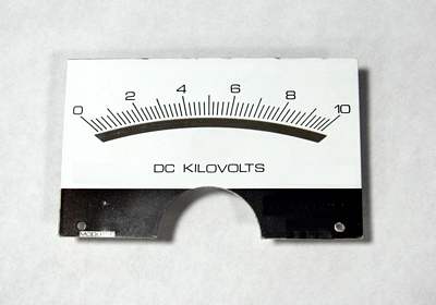
This is what the assembly looks like after you do those things and look at the front.
Use scissors to trim the edge of the printout.
As an alternative you may use a "hobby knife" with a sharp blade.
After the four sides are trimmed use the hobby knife to trim the area around the pointer bearing.
From the front side use a small pen, pencil or other pointed object to clear out the mounting holes.
Open the meter case,
replace the plate,
close the case,
admire your work.
Fin !
Copyright © 2005-2017 James L. Tonne. All rights reserved.